Cold-Wall Retort Furnaces for Residual Debinding and Sintering
Two variants, tailored to different sintering processes, are available for debinding and sintering MIM components.

Función y equipamiento


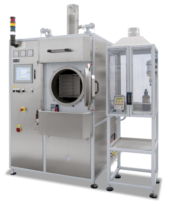
The cold wall retort furnaces of the VHT series are designed as high-temperature furnaces, including graphite or molybdenum/tungsten heating. The vacuum-tight retort allows heat treatment processes either under flammable or non-flammable process gases or in a vacuum.
Two variants, tailored to different sintering processes, are available for debinding and sintering MIM components.
- Switchgear and controller integrated in the housing (from VHT 160/15 .. MIM separate switchgear)
- PLC process control with safety monitoring (F-PLC) and graphic touch panel
- Automatic pre-program, including leak test and safe inertization of the process chamber
- Redundant safety-relevant sensors and valves
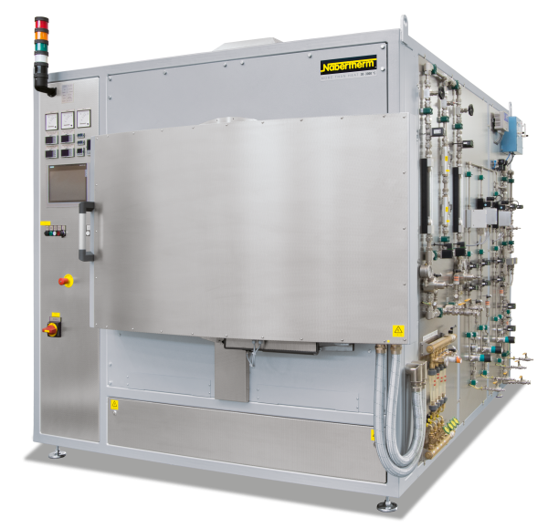
- Process gas management with mass flow controllers (MFC)
- Single-stage rotary vane pump for pre-evacuation
- Water-cooled, stainless steel process chamber
- Over-temperature limiter with manual reset as over-temperature protection
- Inner process box with shelves
- Automatic door lock
- Heated, controllable exhaust gas line with condensate trap
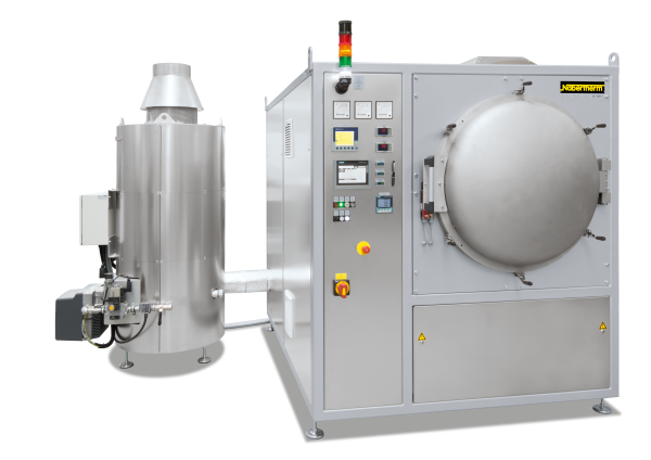
- Exhaust gas torch (gas-fired) for post combustion
- Protective gas emergency flood container for purging the furnace in case of malfunction
Cold-Wall Retort Furnaces for Sintering in Hydrogen
The VHT ../15-MO MIM design is based on the product line with molybdenum/tungsten heating unit and insulation and a hydrogen safety package. The core of this design is a tried and tested safety package that enables safe operation at all times and initiates an appropriate emergency program in the event of a malfunction.
This design is the best choice for sintering stainless steel.
- Can be used for sintering processes in flammable and/or non-flammable process gases or in high vacuum
- Tmax 1500 °C (optional to 1800 °C)
- Max. vacuum, depending on type of pump used, to 2x10⁻⁶ mbar
- H2 introduced into the furnace with controlled overpressure (10-50 mbar relative) from room temperature
- Underpressure operation (optional): Hydrogen introduced into the furnace with controlled under pressure from 750 °C furnace temperature
Cold-Wall Retort Furnaces for Sintering in Inert Gas
Furnaces in the VHT ../15-GR MIM range are equipped with graphite heating and insulation as well as a safety package for residual debinding and sintering with non-flammable process gases.
This design is a very good choice for sintering low-alloyed steel.
- For sintering processes in non-flammable process gases or in vacuum
- Tmax 1500 °C (optional to 2400 °C)
- Max. vacuum, depending on type of pump used, to 2 x 10⁻⁴ mbar
Inner Process Box for Residual Debinding
Due to the release of residual binders before the sintering process, the furnace chamber is equipped with an additional inner process box through which the exhaust gas is directly vented to the exhaust stack. This system significantly reduces contamination of the furnace chamber by gases generated during the debinding step. In addition to optimizing temperature uniformity, the process inner box ensures excellent gas flow across the components due to the gas distribution plate on the rear wall. For a graphite furnace, the inner box is made of graphite, while for a metallic-heated furnace, a box made of molybdenum (potentially tungsten-reinforced) is used.
The standard equipment for sintering furnaces includes a complete set of carrier shelves, as listed in the table. Adjustments to the usable space and the inner process box when using carrier shelves with different dimensions are optionally possible.
Heated Gas Outlet
To minimize binder condensation in the exhaust gas line as much as possible, the area of the gas outlet between the outlet from the inner process box and the torch is heated with heating tapes and, if necessary, is also insulated.
For optimum temperature management of the exhaust gas to the torch, depending on the size of the furnace, the exhaust gas line is divided into different zones. In these zones, the temperatures of the heating tapes can be controlled differently depending on their position.