Uszczelnione piece komorowe z cyrkulacją powietrza
Obie wersje różnią się tym, że wariant I ma tylko uszczelnioną obudowę zewnętrzną, natomiast w przypadku wariantu SI skrzynka wewnętrzna jest zespawana, co prowadzi do mniejszej zawartości tlenu szczątkowego.
Funkcja i wyposażenie

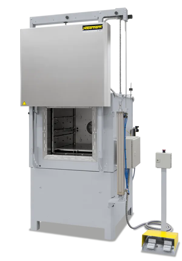
Sealed forced convection chamber furnaces are suitable if a heat treatment process up to 850 °C requires a protective gas atmosphere that does not have to be completely oxygen free. The difference between the two variants is that the I-model only has a sealed outer housing while the SI-model has a welded inner box, which further reduces the residual oxygen concentration.
NA(T)-I design
Like forced convection chamber furnaces < 675 l with the following changes
- Tmax 650 °C and 850 °C
- Silicone door seal
- Furnace housing sealed with silicone
- Protective gas connection in the back wall
- Residual oxygen concentration < 1 % depending on the volume and type of protective gas
- For non-flammable protective and reaction gases such as argon, nitrogen, and forming gas (national regulations must be considered)
- Defined application within the constraints of the operating instructions
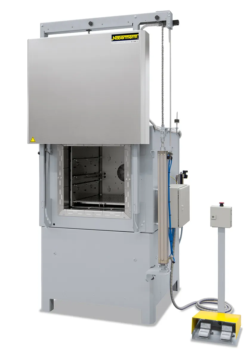
NA-SI design
Additional features
- Tmax 650 °C
- Welded inner housing
- 2-sided heating and air circulation
- Door sealed with seal gas
- Sealed connection to circulation motor
- Gas inlet via circulator shaft
- Residual oxygen concentration to 0.1 % depending on the volume and type of protective gas
- For non-flammable protective and reaction gases such as argon, nitrogen, and forming gas (national regulations must be considered)
- Defined application within the constraints of the operating instructions

Katalogu
Kompletny przegląd naszej szerokiej oferty pieców i akcesoriów przeznaczonych do różnych procesów prowadzonych w atmosferze gazów reakcyjnych palnych i niepalnych, w kąpieli solnej lub w próżni można znaleźć w naszym katalogu „Technologia procesów termicznych 2”.