Piece komorowe i do podgrzewania form i narzędzi
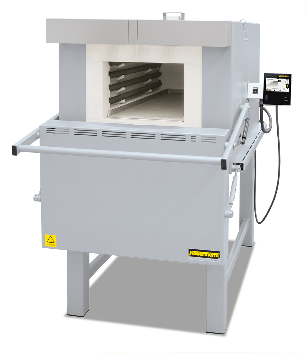
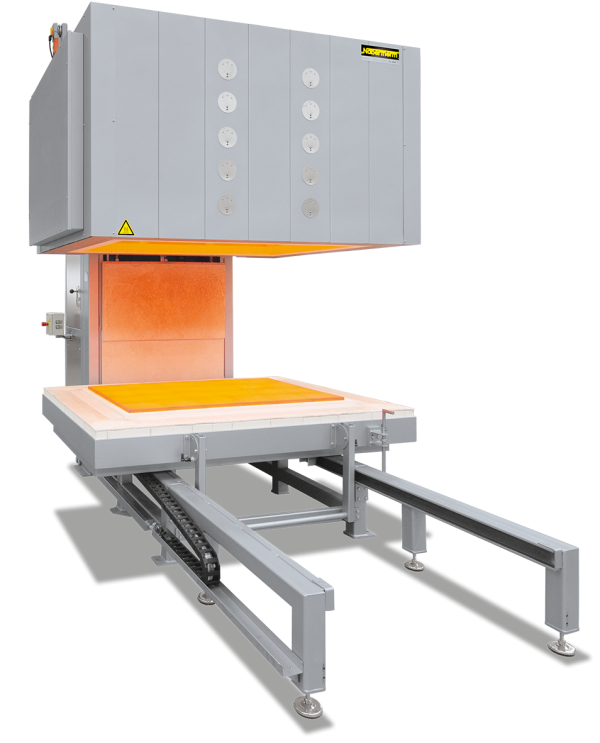
Elementy grzewcze na rurach nośnych zapewniają swobodne promieniowanie ciepła i długą żywotność urządzenia.
Funkcja i wyposażenie
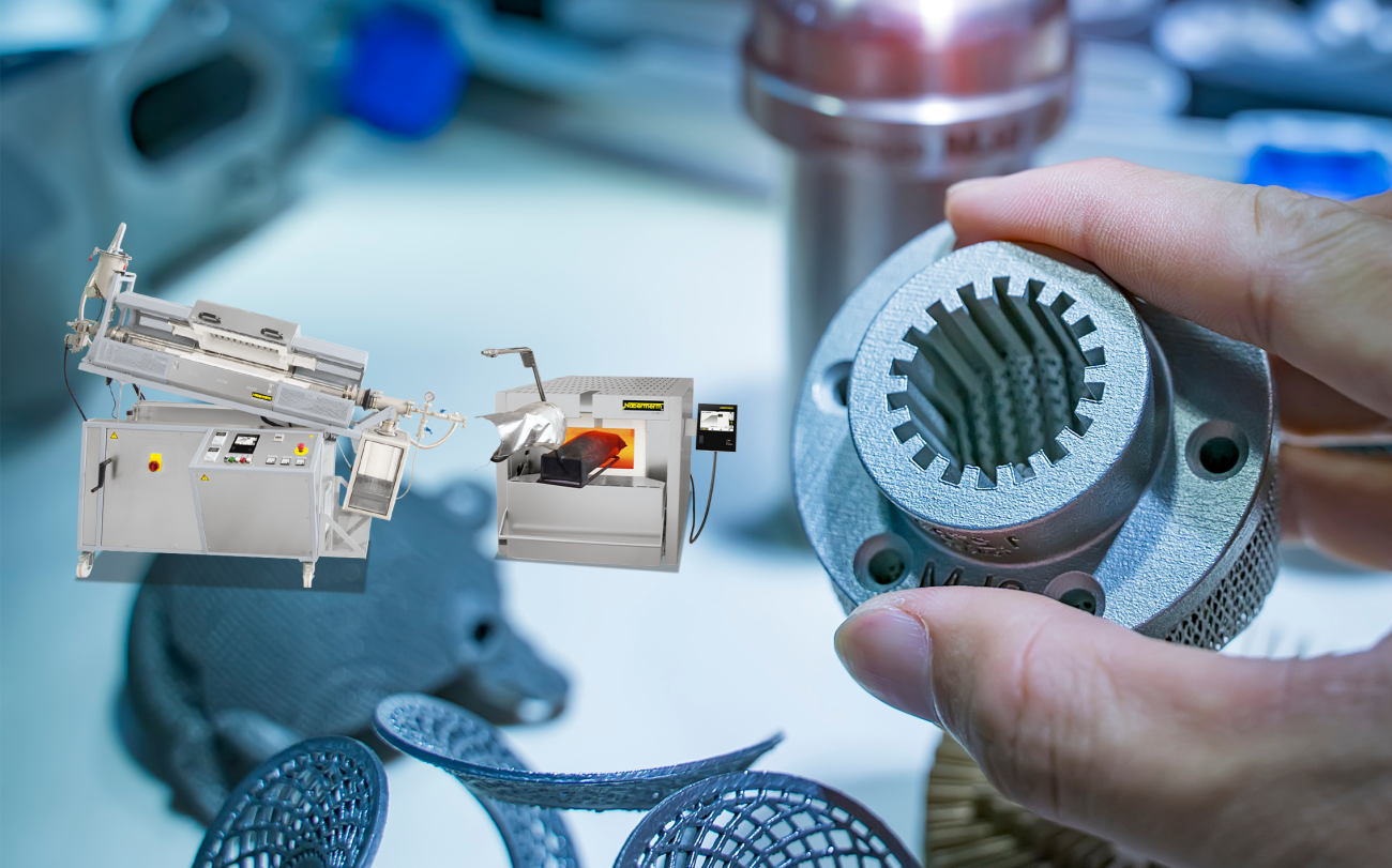
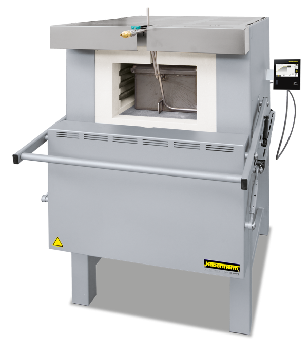
These universal chamber furnaces with radiation heating have been specifically designed to withstand heavy-duty use in the tool shop and industry. They are particularly useful for processes such as tool making or for hardening jobs, e.g. annealing, hardening and forging. With help of various accessories, these furnaces can be customized to your application requirements.
- Compact, robust design construction with double-walled housing
- Door can be opened when furnace is hot
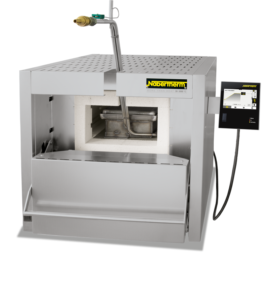
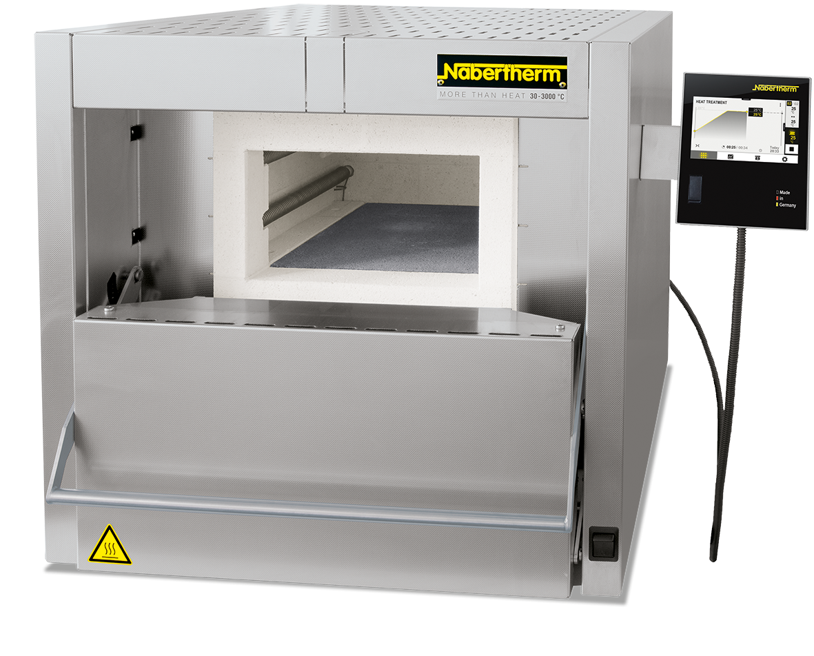
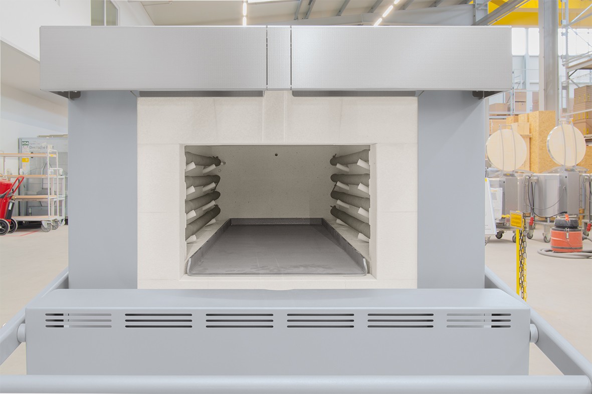
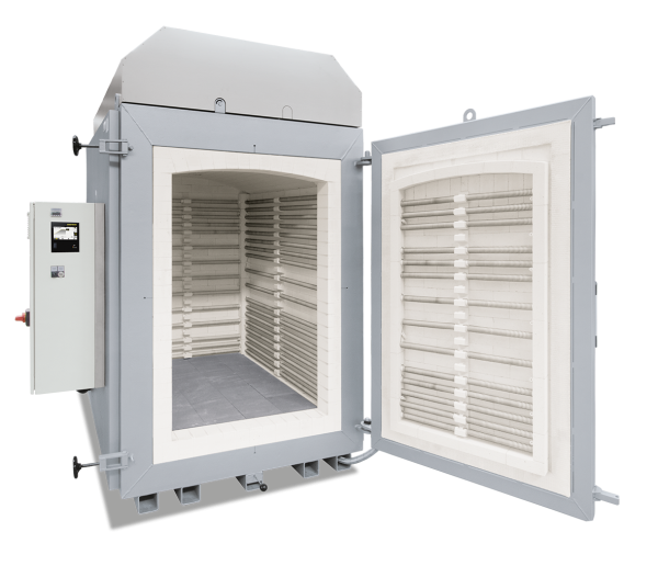
- Deep furnace chamber with three-sides heating: from both side walls and bottom
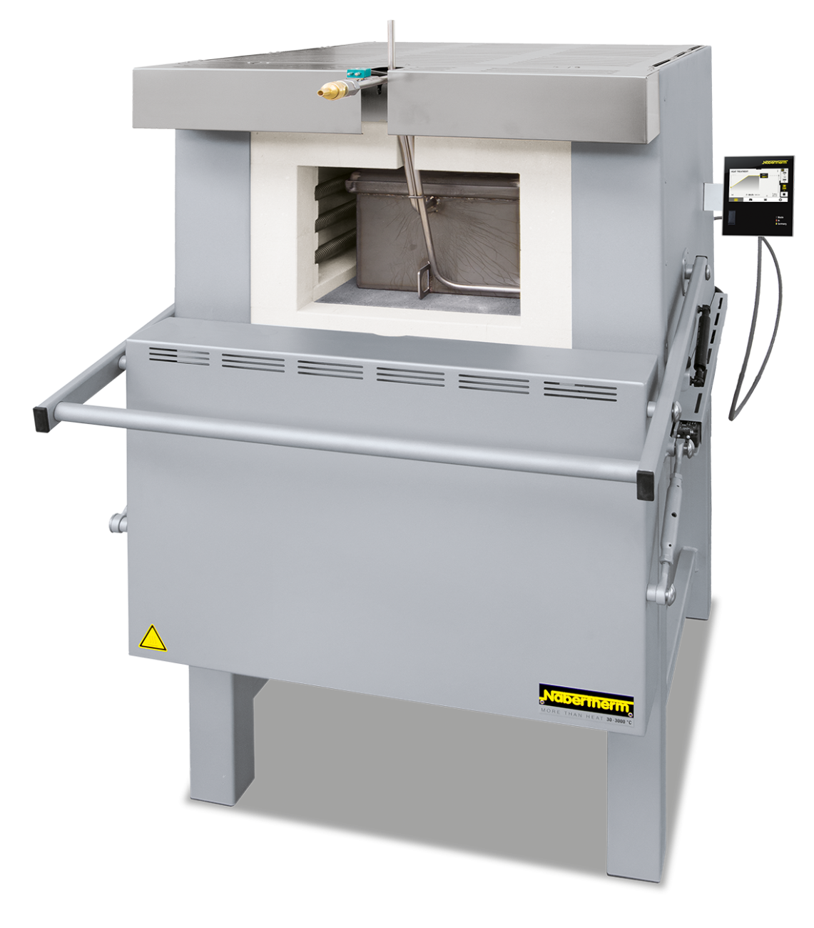
- Heating elements on support tubes ensure free heat radiation and a long service life
- Bottom heating protected by heat-resistant SiC plate (models N 81/.. - N 641/.. also with side SiC plates)
- Stainless steel upper door jamb protects furnace structure when furnace is opened hot up to model N 87/H, models N 81/... - N 641/.. with compact stainless steel door
- Temperature uniformity up to +/− 10 °C according to DIN 17052-1
- Low energy consumption due to multi-layer insulation
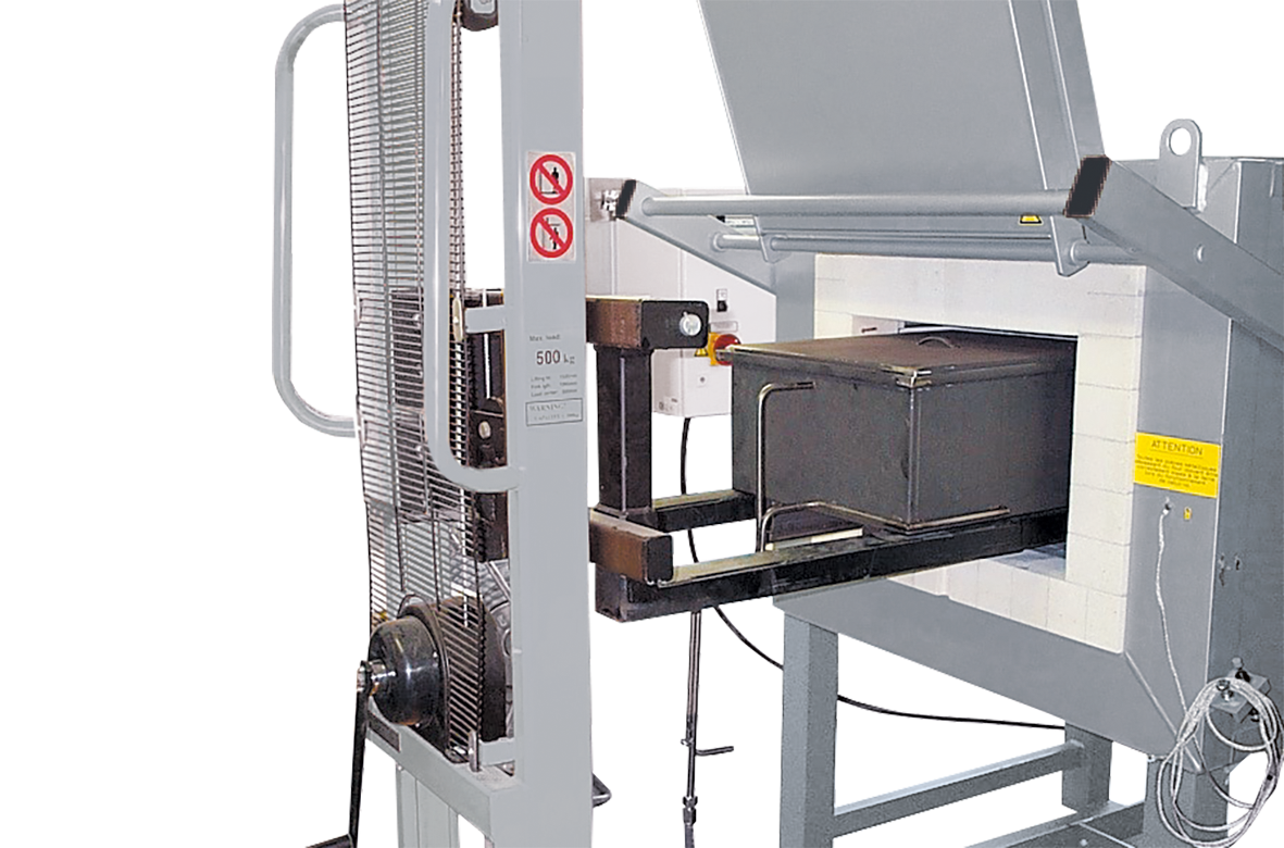
- Base frame included in the delivery, N 7/H - N 17/HR designed as table-top model
- Exhaust opening in the side of the furnace, or on rear wall of chamber furnace in the N 31/H models and higher
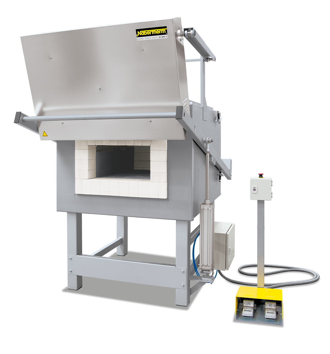
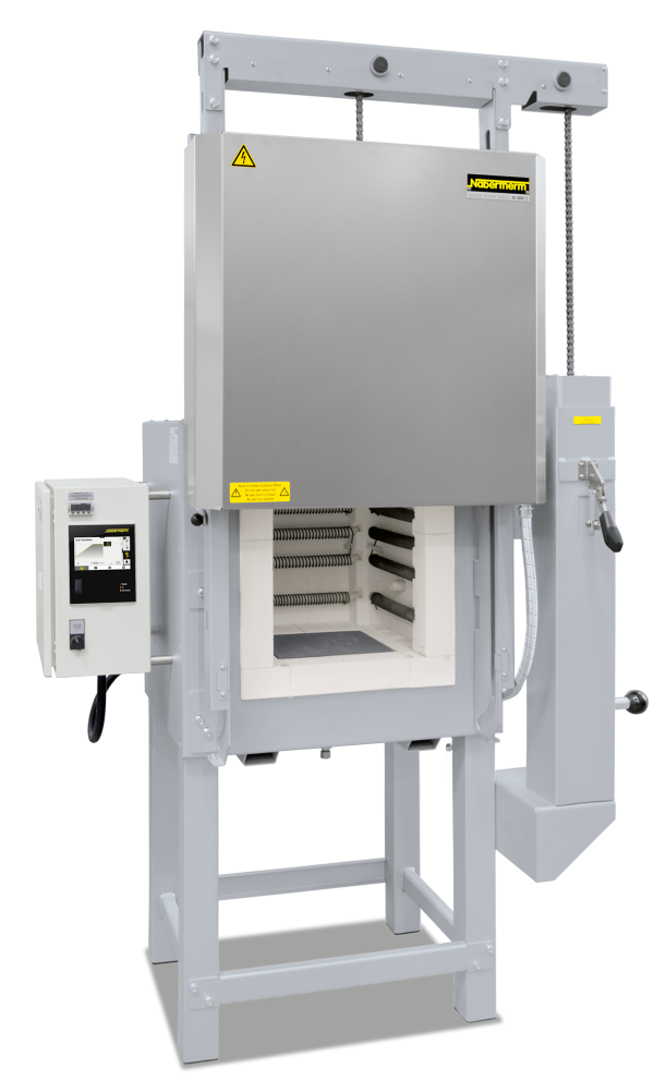
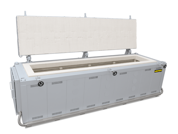
- Parallel swinging door (user protected from heat radiation), up to N 87/H guided downwards, from N 81 guided upwards
- Door movement cushioned with gas dampers/struts
- Heat resistant zinc paint for protection of door and door frame (for model N 81 and larger)
- Over-temperature limiter with adjustable cutout temperature as temperature limiter to protect the furnace and load
- Exclusive use of insulation materials without categorization according to EC Regulation No 1272/2008 (CLP). This explicitly means that alumino silicate wool, also known as “refractory ceramic fiber” (RCF), which is classified and possibly carcinogenic, is not used.
- Defined application within the constraints of the operating instructions
- NTLog Basic for Nabertherm controller: recording of process data with USB-flash drive
- Controller with touch operation B500 (5 programs with 4 segments each)
- Freeware NTEdit for convenient program input via ExcelTM for WindowsTM on the PC
- Freeware NTGraph for evaluation and documention of firings using ExcelTM for WindowsTM on the PC
- MyNabertherm App for online monitoring of the firing on mobile devices for free download
Dalsze produkty

Katalogu
Kompletny przegląd naszej szerokiej oferty pieców z wysuwnym trzonem, pieców kołpakowych, pieców do topienia szkła i innych modeli do obróbki szkła można znaleźć w naszym katalogu „Technika światłowodowa / Szkło”.