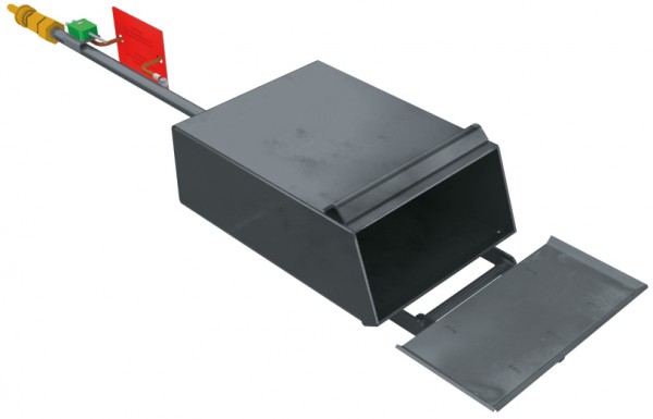
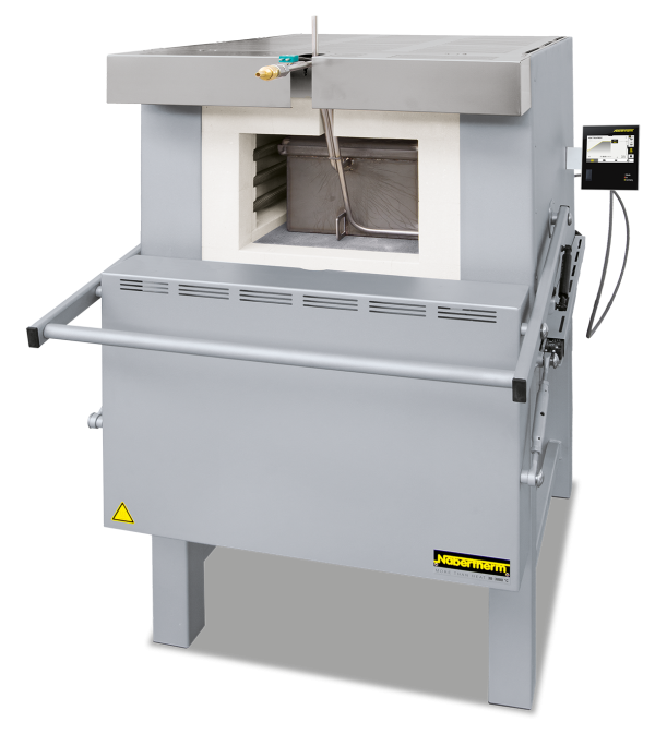
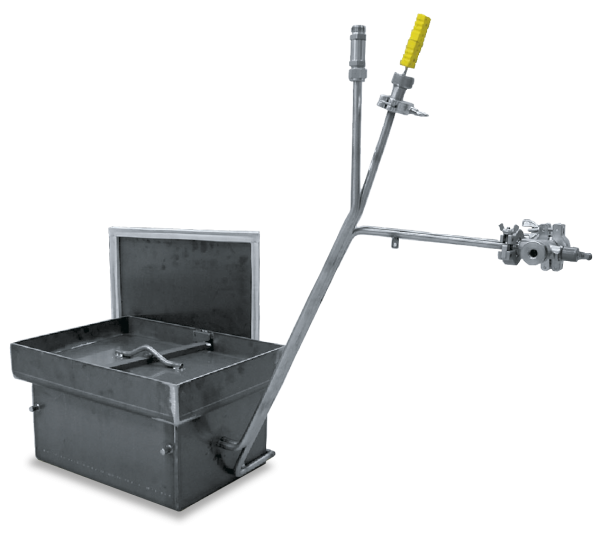
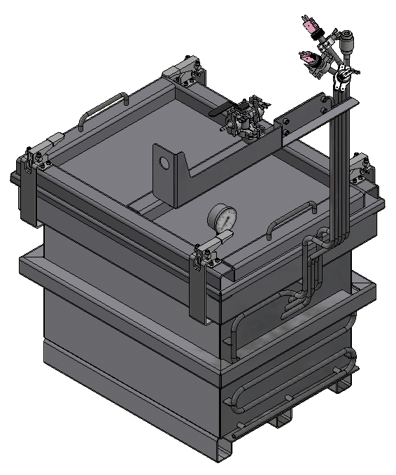
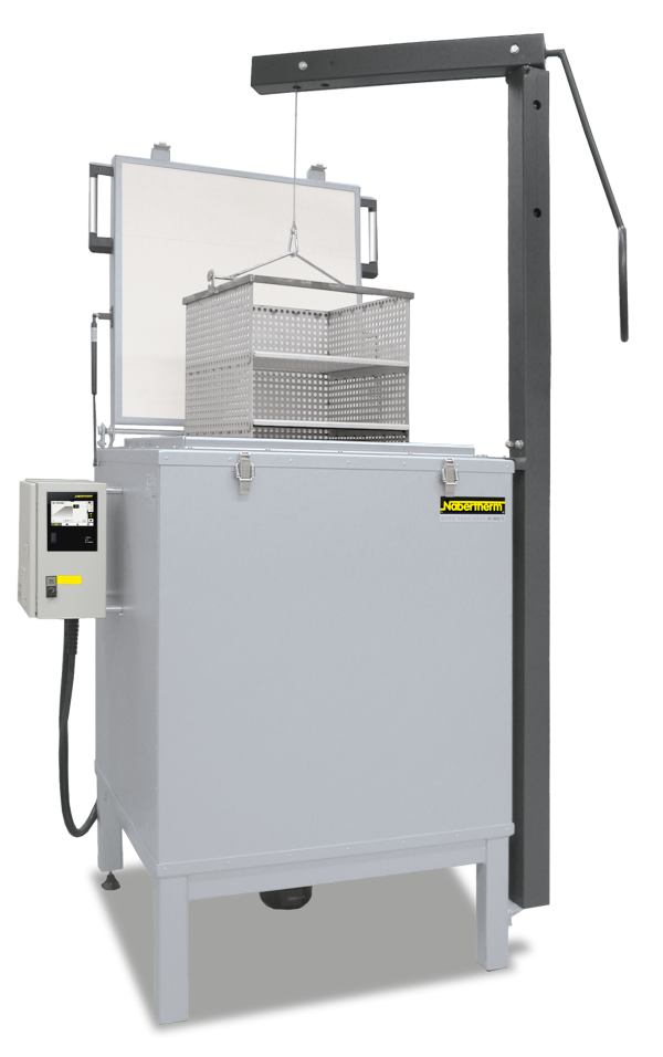
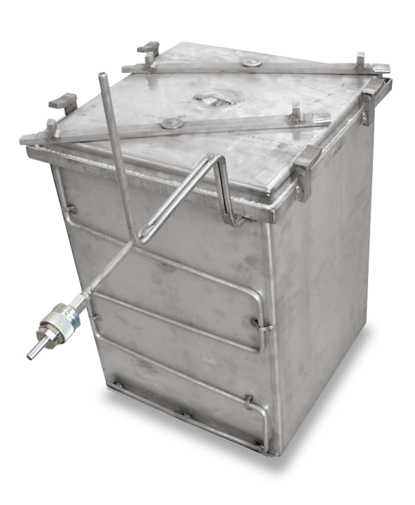
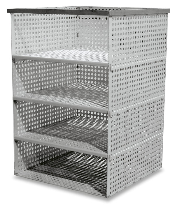
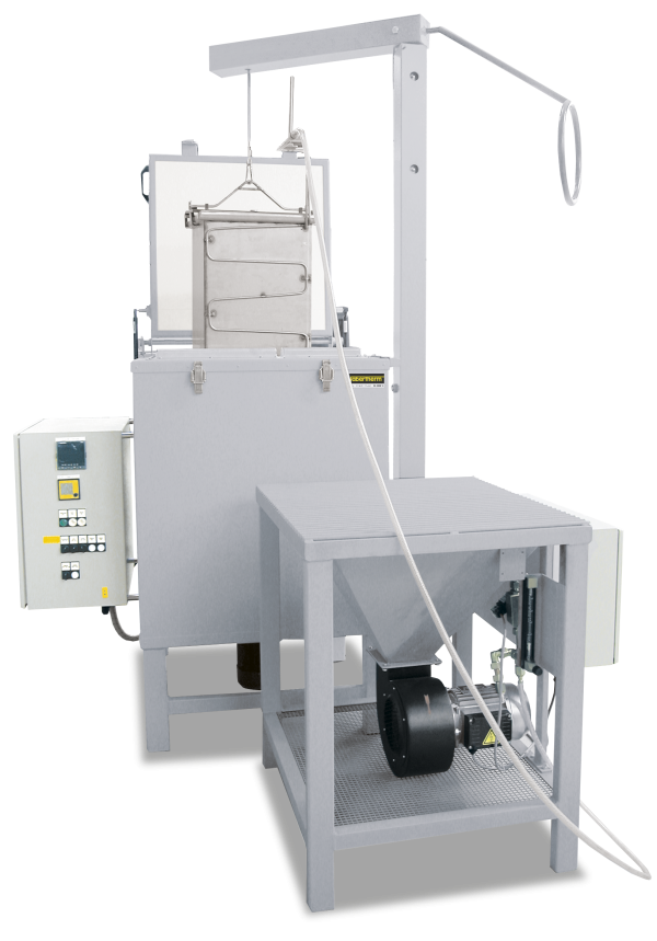
Skrzynki gazowe z zamykaną pokrywą do modeli N 7/H – N 87/H do pozostawienia w piecu
Do sukcesywnej obróbki cieplnej poszczególnych elementów w gazie osłonowym.

Funkcja i wyposażenie
Working with Protective Gas Boxes with Hinged Lid in continuous Operation
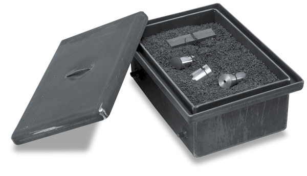
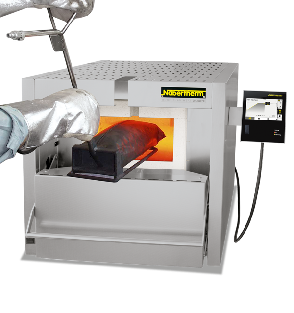
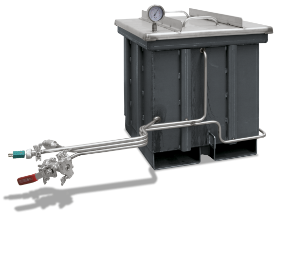
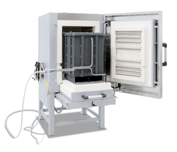
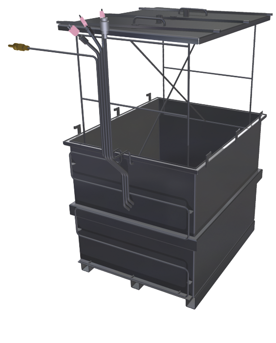
In the case of successive protective gas heat treatment of individual parts, a gassing box is recommended, which remains in the furnace. For charging, the box is equipped with a flap lid to the front. The lid closes without a sealing profile against the oblique position of the box opening. Larger gas losses in comparison with removable boxes can be expected. For the protective gas supply the pipe goes through a bore on the rear wall of the furnace. For charging, the box is opened in the furnace using a draw hook and the workpieces are placed into the box. The box is continuously flushed with non-flammable protective and reactive gases such as argon, nitrogen or forming gas 95/5. Due to a slight overpressure within the box the protective gas is vented off through the hinged lid. After the heat treatment the box is opened using a draw hook and the workpieces are removed.
- Tmax 1100 °C
- For non-combustible protective and reactive gases argon, nitrogen and forming gas (observe national regulations)
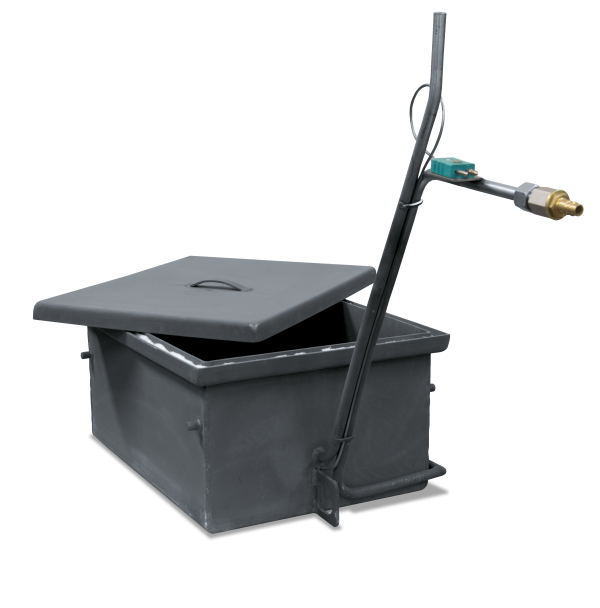
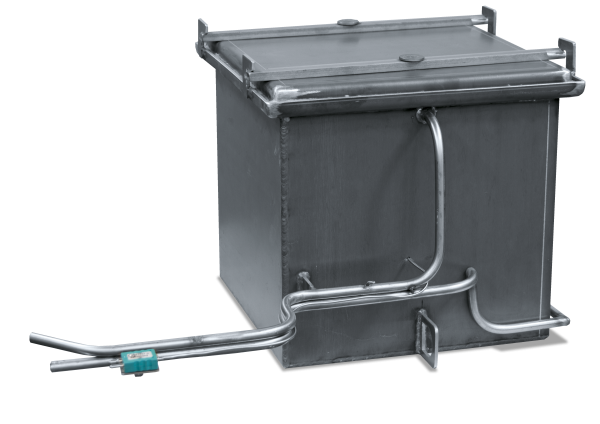
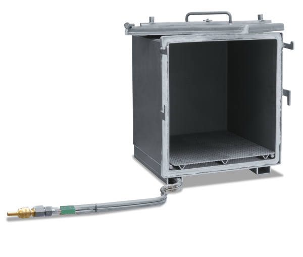
- Protective gas box with flap lid and gas supply from the rear wall
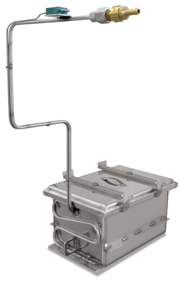
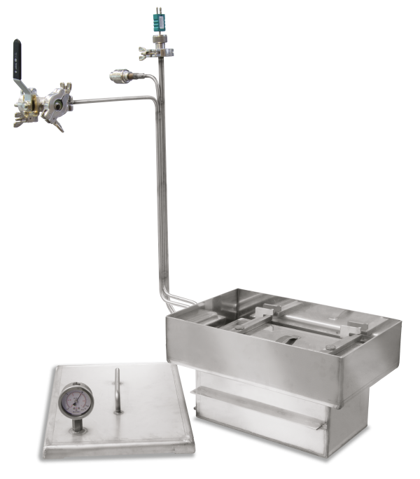
- Protective gas connection via quick coupling with hose connector (inner diameter 9 mm)
- Piping for gas inlet and outlet through the rear wall
- Front flap lid which opens downwards
- Heat-resistant alloy 314 (AISI)/(DIN material no. 1.4841)
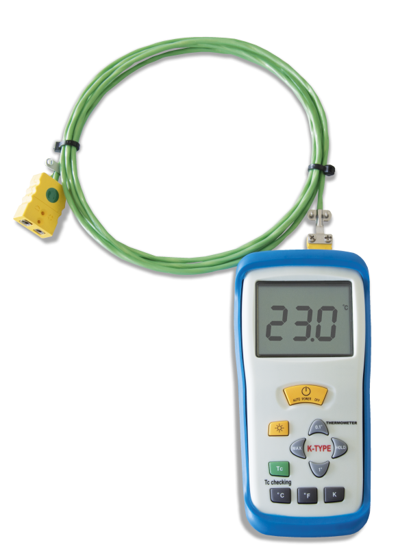
- Charge thermocouple type K for temperature display or charge control
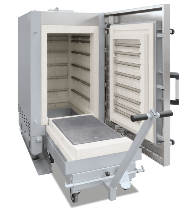
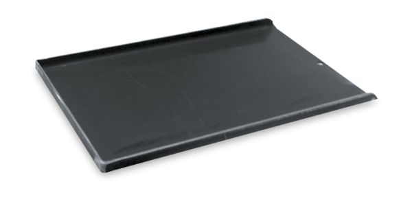
- The furnace will not be equipped with a charging plate (protective gas box is permanently installed)
Dodatkowe wyposażenie
Additional equipment
- Digital temperature display
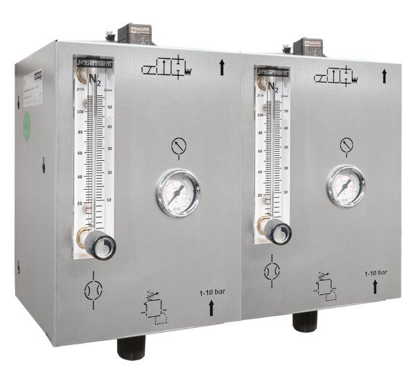
- Gas supply systems
Specyfikacja techniczna
| Article no. | Furnace | Inner dimensions in mm | Outer dimensions in mm1 | Preflush rate | Process flush rate | ||||
|---|---|---|---|---|---|---|---|---|---|
| w | d | h | W | D | H | l/min | l/min | ||
| 631000965 | N 7/H | 170 | 170 | 80 | 213 | 221 | 114 | 15 - 20 | 5 - 8 |
| 631000970 | N 11/H, N 11/HR | 170 | 270 | 80 | 213 | 321 | 114 | 15 - 20 | 5 - 8 |
| 631000975 | N 17/HR | 170 | 420 | 80 | 213 | 471 | 114 | 15 - 20 | 5 - 8 |
| 631000980 | N 31/H | 270 | 260 | 190 | 303 | 321 | 224 | 20 - 25 | 10 - 15 |
| 631000984 | N 41/H | 270 | 410 | 190 | 303 | 471 | 224 | 20 - 25 | 10 - 15 |
| 631000988 | N 61/H | 270 | 660 | 190 | 303 | 721 | 224 | 20 - 25 | 10 - 15 |
| 631000990 | N 87/H | 270 | 910 | 190 | 303 | 971 | 224 | 20 - 25 | 10 - 15 |
| Work space = box inner dimensions: - 30 mm to all sides1 Without piping Larger boxes and custom dimensions available upon request |
|||||||||
Zapytanie ofertowe
Dalsze produkty
Katalogu
Kompletny przegląd naszej szerokiej oferty pieców i akcesoriów przeznaczonych do różnych procesów prowadzonych w atmosferze gazów reakcyjnych palnych i niepalnych, w kąpieli solnej lub w próżni można znaleźć w naszym katalogu „Technologia procesów termicznych 2”.
