Gas Feed Boxes with Hinged Lid for Models N 7/H - N 87/H which Remain in the Furnace
In the case of successive protective gas heat treatment of individual parts.

Function and equipment


Working with Protective Gas Boxes with Hinged Lid in continuous Operation
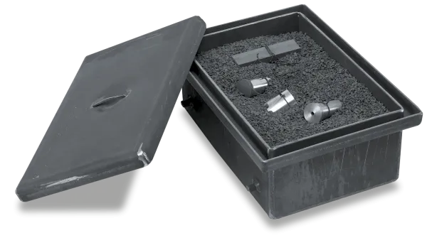
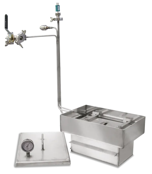
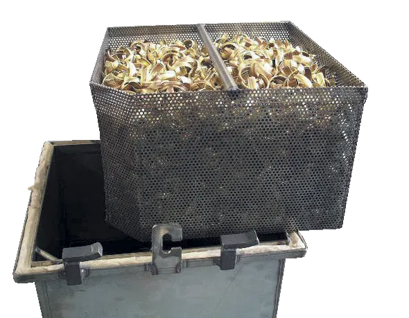
In the case of successive protective gas heat treatment of individual parts, a gassing box is recommended, which remains in the furnace. For charging, the box is equipped with a flap lid to the front. The lid closes without a sealing profile against the oblique position of the box opening. Larger gas losses in comparison with removable boxes can be expected. For the protective gas supply the pipe goes through a bore on the rear wall of the furnace. For charging, the box is opened in the furnace using a draw hook and the workpieces are placed into the box. The box is continuously flushed with non-flammable protective and reactive gases such as argon, nitrogen or forming gas 95/5. Due to a slight overpressure within the box the protective gas is vented off through the hinged lid. After the heat treatment the box is opened using a draw hook and the workpieces are removed.
- Tmax 1100 °C
- For non-combustible protective and reactive gases argon, nitrogen and forming gas (observe national regulations)
- Protective gas box with flap lid and gas supply from the rear wall
- Protective gas connection via quick coupling with hose connector (inner diameter 9 mm)
- Piping for gas inlet and outlet through the rear wall
- Front flap lid which opens downwards
- Heat-resistant alloy 314 (AISI)/(DIN material no. 1.4841)
- Charge thermocouple type K for temperature display or charge control
- The furnace will not be equipped with a charging plate (protective gas box is permanently installed)
Further products


Catalog
A complete overview of our extensive range of furnaces and accessories for various processes that take place under flammable or non-flammable reaction gases, in a salt bath or under vacuum can be found in our catalog "Thermal Process Technology 2".

