Continuous Furnace for Burn-Out and Firing/Sintering
The furnace series is designed to meet the high requirements of the electronics industry and modern production.
Function and equipment
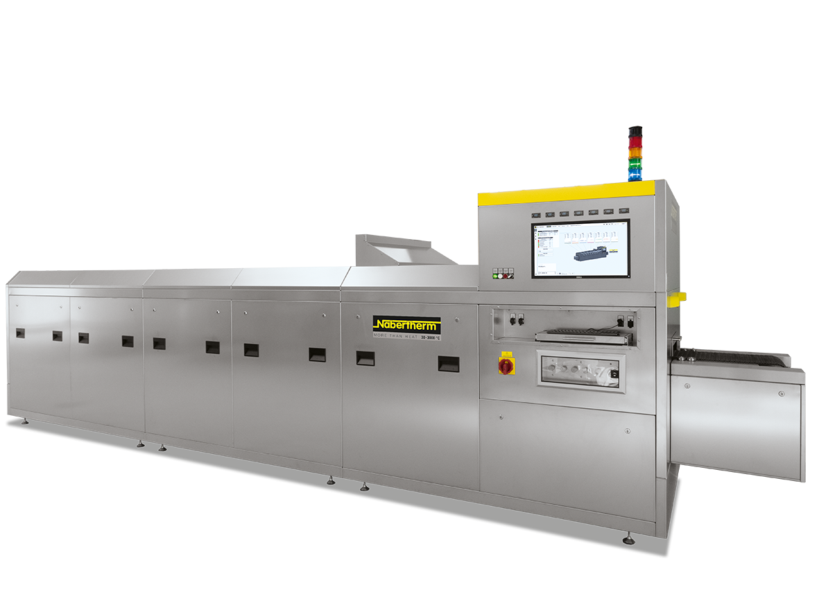


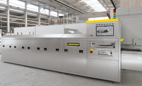
The continuous furnaces of the DF series are designed for continuous processes in air and are therefore suitable for thick-film applications and LTCC firing processes. The product (usually charged on a carrier plate) is moved through the furnace on a metal belt, loading and unloading takes place at approx. 500 mm long entry and exit zones in front of and behind the furnace.
The temperature curve for the process can be adjusted to suit product requirements via the several control zones located one behind the other and via the belt speed (adjustable between approx. 20 - 300 mm/min). The maximum working temperature (peak temperature) can be up to 1050 °C. The temperature uniformity across the belt is crucial for the product quality, the uniformity across the belt is specified with +/− 2K in the empty furnace.
The schematic diagram shows the DF furnace in detail:
In the loading area [1], the charge is positioned on the metal belt and conveyed into the first furnace zone (burn-out zone, [2]) to evaporate the binders from the charge. In this zone, clean dry air (CDA) is injected in counterflow to the belt movement to prevent the formation of an explosive atmosphere. This also means that the exhaust gases are optimally removed from the furnace via appropriate outlets in the furnace ceiling. After the subsequent sintering zone [3], the charge is cooled down by indirect water cooling [4] so that it can be removed at the furnace exit [5].
The furnace series is designed to meet the high requirements of the electronics industry and modern production. The Nabertherm Control Center is therefore already included as standard for control, visualization and documentation (specifically designed for continuous processes). Since a compact design is crucial for these furnaces, the operator interface, all control elements and the switchgear are completely integrated into the furnace housing [6], so that no additional components need to be set up.

Schematic diagram of the continuous furnace DF 36/320/5/10 W
1 Loading area
2 Burn-out zone
3 Sintering zone
4 Cooling zones
5 Furnace exit
6 Controls and switchgear
- Tmax 1050 °C
- Dual shell ventilated housing made of textured stainless steel sheets for low surface temperature and high stability
- Exclusive use of insulation materials without categorization according to EC Regulation No 1272/2008 (CLP). This explicitly means that alumino silicate wool, also known as “refractory ceramic fiber” (RCF), which is classified and possibly carcinogenic, is not used.
- Temperature uniformity across the belt width +/− 2 °C
- Metal belt with adjustable speed (20 - 300 mm/min)
- Maximum charging weight 20 kg/m2
- Charging length 500 mm
- Workspace height 50 mm
- Independent over-temperature protection monitoring for each heating zone
- Three process zones: Burn-out, sintering and cooling
- Passive safety system for debinding in the burn-out zone of the furnace
- Indirect water cooling in cooling zone
- Operator interface integrated in the housing, control and documentation via Nabertherm Control Center (NCC) for continuous processes
- Defined application within the constraints of the operating instructions
Further products
Catalog
A complete overview of our extensive range from the small laboratory furnace up to a combi furnace system for debinding and sintering in one process can be found in our catalog “Advanced Materials”.