Protective Gas Boxes with Evacuation Lid for Models N 7/H - N 161/13
These boxes are equipped with a lid for top charging, protective gas inlet and outlet as well as a evacuation lid with rubber sealing gasket.

Function and equipment

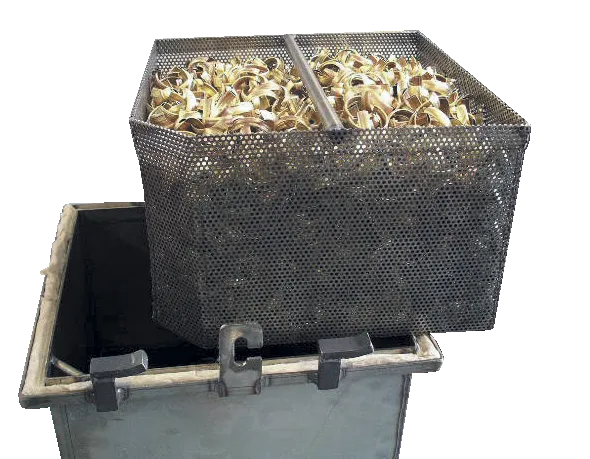
For heat treatment of bulk goods and hollow parts under protective gas atmosphere we recommend the usage of protective gas boxes with an additional evacuation lid. These boxes are equipped with a lid for top charging, protective gas inlet and outlet as well as a evacuation lid with rubber sealing gasket. Gas ductwork and handling while hot is the same as the protective gas boxes described on page 37. In addition, these boxes also feature a connection for a vacuum pump with a shut-off valve. After charging the box in a cold state it is evacuated and afterwards flushed with protective gas. By repeating this process once or several times the results are considerably improved. After the box was flushed with protective gas the last time, the evacuation lid is removed and the box is placed into the preheated furnace. Protective gas is used for heat treatment. Thus traces of oxygen in the box can be reduced by a considerable amount which improves the quality of the components accordingly. After the heat treatment the box is taken out of the furnace and can be cooled in air or be opened to remove the charge. The box can also be force-cooled on a cooling platform while closed. Be sure that the protective gas flowrate is increased for this application.
- Tmax 1100 °C
- For non-combustible protective and reactive gases argon, nitrogen and forming gas (observe national regulations)
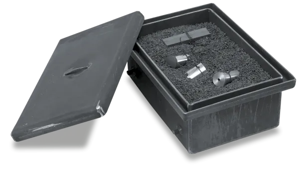
- Protective gas box with fiber sealing and lid with locks, recess for evacuation lid, gas inlet via a pipe into the bottom of the box
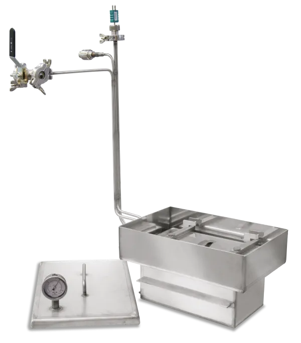
- Evacuation lid with rubber sealing (Elastomer) and manometer
- Protective gas connection via threeway ball valve and quick coupling with hose connector (inner diameter 9 mm)
- Piping for gas inlet and outlet through the furnace collar
- Heat-resistant alloy 314 (AISI)/(DIN material no. 1.4841)
- Charge thermocouple type K for temperature display or charge control
Further products


Catalog
A complete overview of our extensive range of furnaces and accessories for various processes that take place under flammable or non-flammable reaction gases, in a salt bath or under vacuum can be found in our catalog "Thermal Process Technology 2".

